
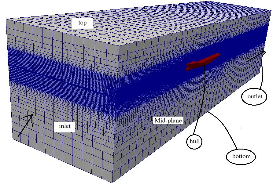
OpenFOAM Boundary Conditions in Foundation 14
Boundary conditions define how an OpenFOAM computational domain communicates with its physical surroundings: where fluid enters and leaves, how pressure is constrained, how a hull interacts with the fluid, and how an open free-surface boundary behaves. In Foundation 14, field boundary conditions are specified in boundaryField dictionaries in files such as 0/U, 0/p, 0/p_rgh and 0/alpha.water. [1]
This guide focuses on marine CFD and distinguishes mesh patch types from field boundary conditions, then explains fixedValue, zeroGradient, inlet/outlet logic, solid walls, symmetry, p_rgh, alpha.water and the open-atmosphere pattern documented in Foundation 14. [3] [6]
The article does not present a universal boundary-condition file. Boundary conditions must match the exact solver formulation, field, physical boundary and OpenFOAM release being used.
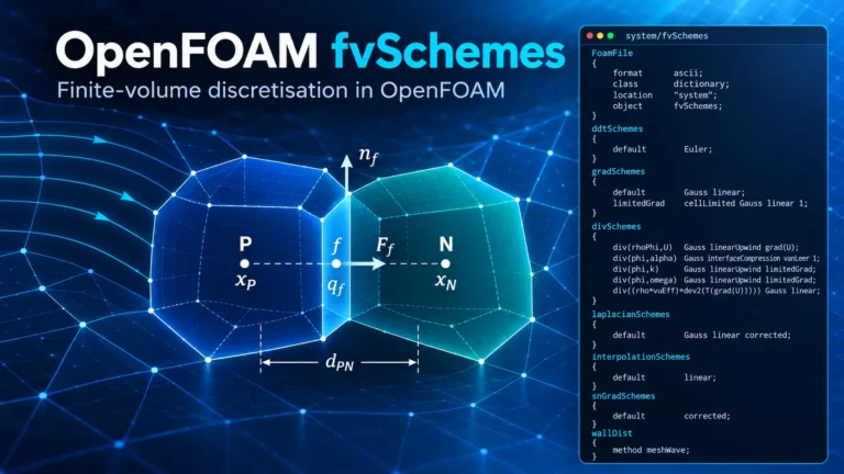
Already covered: numerical discretisation choices are explained separately in the OpenFOAM fvSchemes guide. For more OpenFOAM tutorials and workflow notes, visit the Software & Workflow Notes archive.
Related Ocean Tech Review guides: OpenFOAM 14 Case Structure, OpenFOAM 14 Solver Architecture, and OpenFOAM 14 controlDict.
1. Where Boundary Conditions Live in OpenFOAM
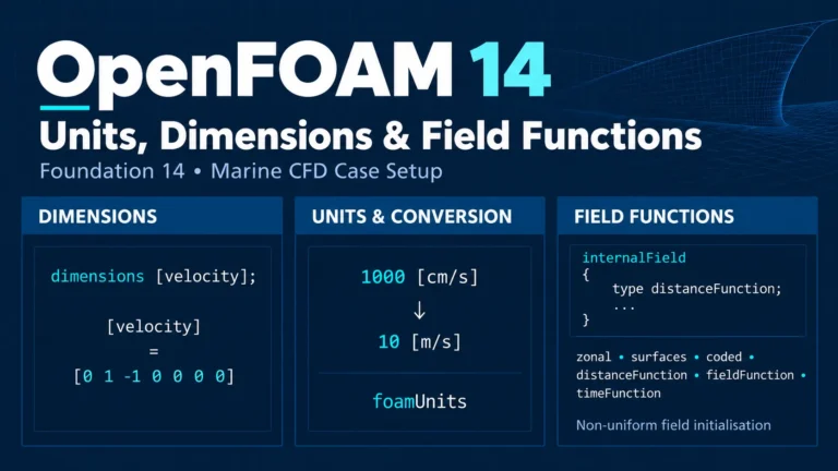
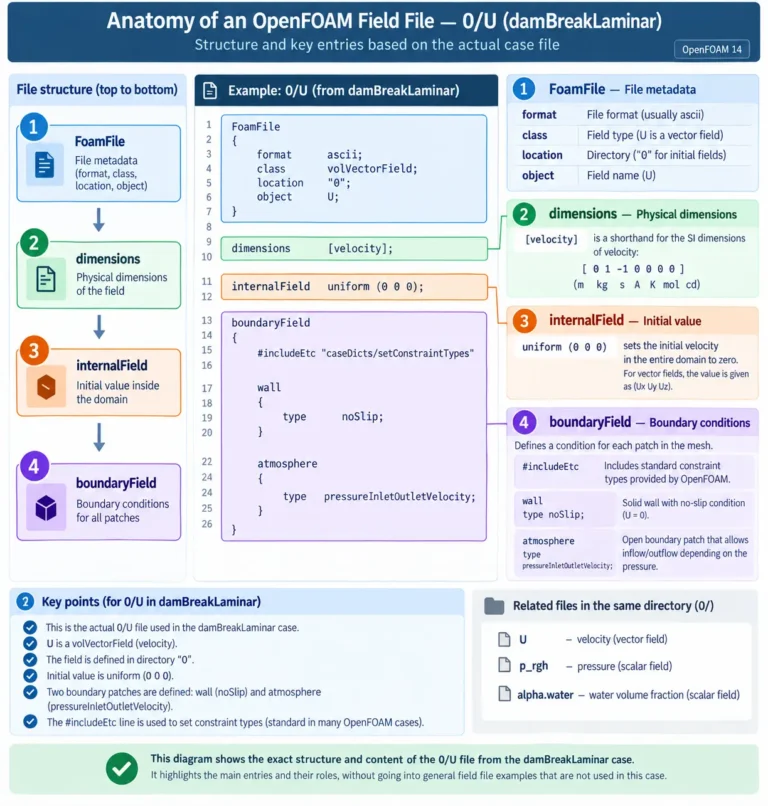
An OpenFOAM field file normally contains the entries dimensions, internalField and boundaryField. Boundary conditions are assigned inside boundaryField for the patches defined by the mesh. Foundation 14 documents this structure directly in the field-file format and boundary-condition chapters. [1] [2]
dimensions      [velocity];
internalField   uniform (0 0 0);

boundaryField
{
    inlet
    {
        type    fixedValue;
        value   uniform (5 0 0);
    }

    outlet
    {
        type    zeroGradient;
    }

    hull
    {
        type    noSlip;
    }
}
The same patch names normally appear in other field files such as p, p_rgh, alpha.water and turbulence variables, but the field boundary-condition type can differ from one field to another. [1]
2. Mesh Patch Type Is Not the Same as a Field Boundary Condition
This distinction is fundamental in OpenFOAM. In the mesh boundary file, a solid hull can be classified as a wall:
hull
{
    type wall;
}
Foundation 14 explains that wall is a mesh patch classification. It identifies the patch as a solid wall and is required by models such as turbulence wall functions and wall-distance calculations, but it does not itself prescribe a velocity or pressure value. [3]
The velocity field on the same patch can use:
hull
{
    type noSlip;
}
while a free-surface pressure field may use fixedFluxPressure, and alpha.water may use zeroGradient when wall adhesion is not modelled. The Foundation 14 dam-break tutorial demonstrates exactly this separation. [6]
Do not equate wall with noSlip. The first describes the mesh patch; the second is a velocity boundary condition.
3. fixedValue: Prescribing a Boundary Value
fixedValue directly prescribes the value of a field on a patch. In mathematical terminology, it is a fixed-value or Dirichlet-type condition.
inlet
{
    type    fixedValue;
    value   uniform (5 0 0);
}
The Foundation 14 field-file example uses fixedValue for inlet velocity. For a basic incompressible subsonic inflow, CFD Direct describes the standard pairing as a fixed value for velocity and other transported quantities together with a zero pressure gradient. [2] [4]
In marine CFD, this is a natural starting point when an incoming current or towing-frame velocity is known. The value or profile itself must still represent the physical problem; the fact that fixedValue is available does not justify an arbitrary inlet specification.
4. zeroGradient: Zero Normal Gradient at the Boundary
The basic zeroGradient condition sets the normal gradient of a field to zero:
∂φ/∂n = 0.
outlet
{
    type zeroGradient;
}
The boundary value is therefore obtained from the interior solution rather than prescribed independently. Foundation 14 uses this as the simple velocity-outlet condition in its field-file example. [2]
For basic incompressible subsonic flow, CFD Direct pairs zero-gradient pressure with a prescribed velocity at the inlet, and fixed pressure with zero-gradient velocity at the outlet. [4]
Important: zeroGradient is not a universal outlet or wall rule. Reverse flow, body forces, hydrostatically reduced pressure and open free-surface boundaries can require derived conditions.
5. Why Velocity and Pressure Boundary Conditions Must Be Paired
Pressure and velocity are coupled in incompressible CFD. They therefore should not be specified independently at open boundaries without considering the mathematical formulation. The fundamental pairing described by CFD Direct is:
| Boundary | Pressure | Velocity / transported fields |
|---|---|---|
| Known inlet | zeroGradient | fixedValue |
| Simple outlet | fixedValue | zeroGradient |
This is the basic subsonic incompressible arrangement, not a universal marine-CFD template. Open boundaries that can entrain fluid, VOF atmospheres and pressure formulations containing gravity require additional logic. [4] [7]
A common setup error is to impose both a velocity and a pressure value simply because both are known approximately from the physical description. That can over-constrain the numerical boundary. The imposed information must match the role of the boundary in the pressure–velocity system.
6. Inlet Boundaries in Marine CFD
A conventional current inlet with a prescribed velocity can use:
inlet
{
    type    fixedValue;
    value   uniform (5 0 0);
}
with a compatible pressure condition, commonly zeroGradient in the basic incompressible pairing. [4]
The inlet does not have to be spatially uniform. Foundation 14 supports field functions in boundary conditions, allowing non-uniform or time-varying specifications where the problem requires them. [17]
For marine work, the inlet profile should come from the physical definition of the simulation, experimental conditions, a justified current profile or another validated source. Boundary-condition syntax is not a substitute for defining the correct incoming flow.
7. Outlet Boundaries and the Problem of Backflow
A simple velocity outlet can use zeroGradient, but a patch named outlet does not guarantee that the local flux always points out of the domain. Recirculation, startup transients, large-scale vortices or moving bodies can cause local inflow through part of a nominal outlet.
CFD Direct’s recommended-boundary-condition guidance explicitly addresses free boundaries that may experience both inflow and outflow. OpenFOAM therefore provides mixed conditions rather than forcing a permanent outflow assumption. [7]
For this reason, outlet behaviour should be checked in the solution. If reverse flow occurs, the correct response is not automatically to move the boundary or change a solver setting; first determine whether the boundary physics and chosen BC can represent the actual inflow/outflow behaviour.
8. inletOutlet: One Patch, Two Flow Directions
inletOutlet is derived from a mixed condition. Foundation 14 defines its behaviour as:
zeroGradient
fixedValue using inletValue
The switch is based on the direction of the patch flux. [5]
atmosphere
{
    type        inletOutlet;
    inletValue  uniform 0;
}
Foundation 14 uses this exact logic for alpha.water at the atmosphere boundary of damBreakLaminar. During outflow the phase fraction has zero gradient; during inflow, alpha.water = 0 is imposed, corresponding to air in that two-phase case. [5] [6]
9. Why Ordinary inletOutlet Is Not Ideal for Velocity at a Pressure Boundary
For a scalar, prescribing a known inflow value through inletOutlet can be straightforward. Velocity is more subtle at a free boundary where pressure is specified because the required inflow speed may need to be determined by the pressure and flux solution rather than chosen in advance.
CFD Direct explains this limitation when discussing inlet–outlet velocity conditions. For such pressure-controlled boundaries, a velocity condition tied to the flux is more appropriate than a generic fixed inflow velocity. [8]
This is the context in which pressureInletOutletVelocity becomes important for open and atmospheric boundaries.
10. pressureInletOutletVelocity for Open Velocity Boundaries
pressureInletOutletVelocity is designed for patches where pressure is specified and the velocity may correspond to either inflow or outflow. In the Foundation 14 dam-break description, the condition applies zero gradient to velocity components for outflow, while for inflow the tangential component is fixed and the normal behaviour follows the flux solution. [6]
atmosphere
{
    type pressureInletOutletVelocity;
}
This is particularly relevant for a free atmosphere boundary because the top boundary must allow fluid to leave and, where the solution demands it, enter the domain. Foundation 14 explicitly uses this condition in its documented free-surface tutorial. [6]
Do not interpret the patch name as the flow direction. A physically open boundary may switch direction locally, which is precisely why mixed pressure-linked velocity conditions exist.
11. Wall Patches and noSlip
A physical hull surface should normally be classified as a wall in the mesh when it is a solid wall. Foundation 14 states that the wall tag is used by models that need wall identity, including wall functions and wall-distance calculations. [3]
For a stationary solid wall, Foundation 14 defines noSlip as a velocity condition that fixes the wall velocity to zero:
hull
{
    type noSlip;
}
The Source Guide explicitly describes noSlip as a stationary-wall velocity condition. [9]
For a stationary hull in an inertial frame, this is the direct field-level statement of the no-slip condition. The pressure and turbulence fields on the same hull require their own appropriate BCs.
12. Moving Hulls and movingWallVelocity
A wall that physically moves with the mesh cannot generally be represented by a zero velocity in the inertial frame. OpenFOAM provides movingWallVelocity for moving rigid or flexible wall surfaces whose mesh vertices move with the surface.
hull
{
    type    movingWallVelocity;
    value   uniform (0 0 0);
}
The Foundation Source Guide describes it as a no-slip velocity condition for moving walls. The value entry is an initial value; the boundary velocity is updated consistently with wall/mesh motion. [10]
This can be relevant to moving-mesh marine simulations, but it should not be treated as a universal replacement for every moving-body technique. The correct condition depends on how the case represents body and mesh motion.
13. Pressure Boundary Conditions on Solid Walls
A common simplified rule is that pressure uses zeroGradient at a wall. That is often appropriate in basic pressure formulations, but it is not a universal OpenFOAM rule.
CFD Direct notes that body forces affect the appropriate pressure-gradient treatment. In free-surface formulations containing gravity and surface tension, Foundation 14 demonstrates a different wall condition: fixedFluxPressure. [7] [6]
The correct question is therefore not simply “Is this a wall?” but also “Which pressure variable is being solved and which body-force terms are present?”
14. fixedFluxPressure and Boundary-Flux Consistency
Foundation 14 defines fixedFluxPressure as a pressure boundary condition that sets the pressure gradient so that the boundary flux matches the flux specified by the velocity boundary condition. [11]
hull
{
    type fixedFluxPressure;
}
In the Foundation 14 dam-break tutorial it is applied to all wall boundaries because the solver includes body forces such as gravity and surface tension. [6]
Marine relevance: free-surface hydrodynamics is gravity-driven, so pressure BCs should be checked against the actual p/p_rgh formulation rather than copied from a body-force-free single-phase case.
15. p vs p_rgh in Marine CFD
Many incompressible cases solve a pressure variable called p. Buoyant and free-surface formulations commonly solve a hydrostatically reduced pressure called p_rgh.
The Foundation Source Guide defines the reduced pressure using the hydrostatic contribution:
prgh = p − ρ g·(h − href). [12]
The practical consequence is important: a BC appropriate for p should not be copied automatically to p_rgh. OpenFOAM provides pressure conditions designed specifically for hydrostatically reduced pressure variables.
16. prghTotalPressure at an Open Atmosphere
Foundation 14 uses prghTotalPressure on the hydrostatically reduced pressure field at the open atmosphere of its dam-break tutorial. The Source Guide documents the required total-pressure value through p0. [6] [13]
atmosphere
{
    type    prghTotalPressure;
    p0      uniform 0;
}
For the same atmosphere boundary, Foundation 14 combines this pressure condition with pressureInletOutletVelocity for U and inletOutlet for other fields such as alpha.water. [6]
17. A Foundation 14 Free-Surface Atmosphere Combination
The documented damBreakLaminar case provides a useful reference pattern for understanding an open top boundary:
| Field | Atmosphere BC | Role |
|---|---|---|
U | pressureInletOutletVelocity | Allows inflow/outflow while remaining consistent with the pressure/flux solution. |
p_rgh | prghTotalPressure | Pressure condition for the hydrostatically reduced pressure variable. |
alpha.water | inletOutlet, inletValue 0 | Zero gradient on outflow; incoming phase is air. |
Foundation 14 explains that this combination is used because the top boundary must permit both outflow and inflow according to the internal flow. [6]
This is a documented example, not a universal prescription for every ship or free-surface domain. Solver formulation, domain design and the physical meaning of the open boundary still govern the final choice.
18. Boundary Conditions for alpha.water
In a water–air VOF case, alpha.water represents the water volume fraction. The Foundation 14 dam-break tutorial uses alpha.water = 1 for water and alpha.water = 0 for air. [6]
At walls in that tutorial:
wall
{
    type zeroGradient;
}
At the atmosphere:
atmosphere
{
    type        inletOutlet;
    inletValue  uniform 0;
}
The latter means that if flow enters through the atmosphere, the incoming phase fraction is air rather than water. Foundation 14 explicitly documents this interpretation. [5] [6]
19. Contact Angle at Solid Surfaces
zeroGradient is not the only possible wall treatment for phase fraction. Foundation 14 notes that VOF surface-tension models can include wall adhesion using an alphaContactAngle boundary condition with a specified contact angle. [6]
The dam-break tutorial intentionally ignores wall-adhesion effects and therefore applies zeroGradient to the phase fraction on walls. That distinction is important: the BC expresses a modelling decision, not a universal property of water against every solid surface.
Detailed wetting and contact-angle modelling is outside the scope of this general marine boundary-condition guide.
20. Symmetry Boundary Conditions
A symmetry boundary represents a mirrored solution across the boundary. Foundation 14 provides symmetryPlane for a perfectly planar symmetry patch and symmetry for the more general constraint. [3]
symmetryPatch
{
    type symmetry;
}
For a scalar field, symmetry corresponds to zero normal gradient. For a velocity-like vector, the normal component is constrained and the behaviour is slip-like at the symmetry surface. [14]
Using symmetry can reduce computational cost, but Foundation 14 cautions that it is not appropriate when the flow itself breaks symmetry, for example through vortex shedding. A symmetric hull geometry alone is therefore not sufficient justification. [3]
21. slip vs symmetry
OpenFOAM also provides a separate slip boundary condition:
side
{
    type slip;
}
The Foundation 14 Source Guide defines it as a slip constraint. [15]
symmetry and slip can produce similar velocity behaviour at a boundary, but they represent different modelling statements. Symmetry asserts that the solution is mirrored across the boundary, whereas slip imposes a slip constraint without, by itself, asserting geometric and solution symmetry.
22. Far-Field and Freestream Boundaries
Some external-flow domains use a free or far-field boundary rather than a patch that behaves permanently as an inlet or outlet. Foundation 14 provides freestream-type conditions for that purpose.
The freestreamVelocity Source Guide documents a free-stream velocity condition and notes that it is designed to operate with the corresponding freestream pressure treatment. [16]
CFD Direct recommends freestream-style treatment when the external flow conditions are known at a genuinely free far-field boundary. [7]
A boundary should not be called “far field” merely because it is numerically distant from the hull. Its physical role and the assumptions embedded in the BC must still match the intended external-flow problem.
23. Turbulence Variables at Inlets, Outlets and Walls
RANS marine CFD introduces transported fields such as k, omega or epsilon. The basic transport logic remains familiar: prescribed values at inlets, zero-gradient or mixed treatment at outlets, and specialised wall conditions at solid surfaces. [18]
OpenFOAM supplies turbulence wall-function boundary conditions for quantities such as omega, epsilon, k and turbulent viscosity. Their detailed selection depends on the turbulence model and near-wall treatment, so they should not be collapsed into one generic “wall BC”.
The same physical hull patch can therefore use noSlip for U, a pressure-gradient condition for p_rgh, and wall-function conditions for turbulence fields.
24. Marine Boundary-Condition Patterns by Physical Boundary
The following table summarises useful documented patterns. It is a reference map, not a universal copy-and-paste template.
| Physical boundary | U | p / p_rgh | alpha.water |
|---|---|---|---|
| Known incompressible inlet | fixedValue | basic pressure: zeroGradient | case-dependent |
| Simple incompressible outlet | zeroGradient | fixed pressure | case-dependent |
| Stationary solid hull | noSlip | formulation-dependent | often zeroGradient if wall adhesion is omitted |
| Moving mesh wall | movingWallVelocity | solver-consistent pressure BC | formulation-dependent |
| Open atmosphere in the Foundation 14 VOF example | pressureInletOutletVelocity | prghTotalPressure | inletOutlet |
| Symmetry boundary | symmetry | symmetry | symmetry |
| Far field | freestream-type condition | compatible freestream pressure condition | field-dependent |
The first two rows follow the fundamental incompressible pairing described by CFD Direct. The open-atmosphere and free-surface wall patterns are grounded in the Foundation 14 dam-break tutorial. [4] [6]
25. A Stationary Hull Example
For a stationary solid hull, start by ensuring that the mesh patch is identified as a wall:
hull
{
    type wall;
}
Then assign the field-level velocity condition:
hull
{
    type noSlip;
}
Foundation 14 supports both statements at their respective levels: the first identifies a solid wall in the mesh, and the second fixes velocity to zero at a stationary wall. [3] [9]
The appropriate pressure BC is formulation-dependent. A basic pressure formulation can use zero-gradient wall pressure, while a free-surface/body-force formulation may require fixedFluxPressure. [7] [11]
26. A Free-Surface Wall Example
The Foundation 14 dam-break wall configuration provides a compact example of how different fields use different BCs on the same solid boundary:
// U
wall
{
    type noSlip;
}

// p_rgh
wall
{
    type fixedFluxPressure;
}

// alpha.water
wall
{
    type zeroGradient;
}
noSlip imposes the stationary wall velocity. fixedFluxPressure makes the pressure gradient consistent with the velocity boundary flux in a formulation containing body forces. zeroGradient for alpha.water reflects the tutorial’s decision not to model wall adhesion. [6] [11]
27. Open Boundaries Require More Than a Patch Named outlet
Patch names are labels for the user; they do not determine the mathematical boundary condition. A patch called outlet does not force fluid to leave the domain.
Its behaviour is determined by the BCs assigned to each field and by the evolving solution. This is why OpenFOAM includes mixed conditions that respond to flux direction. The Foundation 14 dam-break atmosphere is an explicit example of a patch that must support both directions. [6]
For marine CFD, the practical rule is simple: name the patch for clarity, but choose the BC from the physics and the solved field.
28. Common Boundary-Condition Mistakes in OpenFOAM
Several recurring errors can be avoided by keeping the mesh, field and solver formulation separate:
1. Treating wall as a velocity BC. It is a mesh classification; the velocity field still needs its own condition. [3]
2. Copying p BCs directly to p_rgh. The hydrostatically reduced variable changes the pressure formulation and supports specialised BCs. [12]
3. Assuming a nominal outlet never experiences inflow. Reverse flow is exactly why mixed conditions such as inletOutlet and pressure-linked velocity conditions exist. [5] [8]
4. Using symmetry because the CAD is symmetric. Foundation 14 warns that symmetry is less applicable when the flow breaks symmetry, such as vortex shedding. [3]
5. Treating a tutorial combination as a universal recipe. Tutorial BCs are authoritative examples for their documented solver and physics, not proof that the same configuration is correct for every marine case.
29. How to Check Available Boundary Conditions in OpenFOAM 14
Foundation 14 provides command-line tools for checking what is actually compiled into the installed release.
List scalar boundary conditions:
foamToC -scalarBCsList vector boundary conditions:
foamToC -vectorBCsThe User Guide also recommends foamInfo for information and example cases associated with a specific boundary condition:
foamInfo totalPressureThese commands are valuable because boundary-condition availability and implementation details are release-specific. [2] [5]
30. Wave Boundary Conditions: What This Article Does Not Cover
Foundation 14 includes dedicated wave boundary conditions, including waveVelocity and waveAlpha. The Source Guide states that they obtain their wave information through the registered waveSuperposition framework. [19] [20]
inlet
{
    type    waveAlpha;
    libs    ("libwaves.so");
    liquid  true;
}
This article stops at that interface. Wave theories, wave properties, generation, absorption and wave-tank setup belong in the dedicated Wave Generation article so that the present guide remains focused on general boundary-condition logic.
31. Frequently Asked Questions
What is the difference between fixedValue and zeroGradient in OpenFOAM?
fixedValue directly prescribes the field value on a patch. zeroGradient sets the normal gradient to zero so the boundary value follows from the interior solution. They are fundamental building blocks for many derived conditions. [1] [4]
Is wall the same as noSlip?
No. wall is a mesh patch classification; noSlip is a velocity boundary condition for a stationary wall. [3] [9]
What boundary condition should velocity use at an outlet?
For a simple incompressible outlet with outward flow, zeroGradient is the fundamental condition. If reverse flow is possible, a mixed pressure-linked velocity condition may be more appropriate depending on the pressure specification. [4] [8]
When should I use fixedFluxPressure?
It is used when the pressure gradient must be adjusted so the boundary flux is consistent with the velocity BC. Foundation 14 demonstrates it for wall pressure in a free-surface case containing gravity and surface tension. [11] [6]
Why does free-surface CFD use p_rgh?
p_rgh is a hydrostatically reduced pressure variable. Because it differs from ordinary p, pressure BCs must be selected for the actual variable solved by the formulation. [12]
What does inletOutlet do?
It applies zeroGradient for outflow and a fixed inletValue for inflow. Foundation 14 uses it for alpha.water on the atmosphere boundary of damBreakLaminar. [5]
What does pressureInletOutletVelocity do?
It is a velocity condition intended for pressure-controlled open boundaries and can respond to both inflow and outflow. Foundation 14 uses it at the open atmosphere in its dam-break tutorial. [6]
What should alpha.water use at an atmosphere boundary?
In the documented Foundation 14 dam-break case, it uses inletOutlet with inletValue 0, so incoming fluid from the atmosphere is air in the water–air VOF formulation. [5] [6]
Can I use symmetry to halve a ship domain?
Only when both the geometry and expected flow support a symmetric solution. Foundation 14 explicitly notes that symmetry becomes less applicable when the flow breaks symmetry, for example through vortex shedding. [3]
32. References
The technical claims in this guide are grounded in OpenFOAM Foundation 14 documentation, the Foundation Source Guide, and CFD Direct’s Notes on Computational Fluid Dynamics. Tutorial-specific configurations are presented as examples rather than universal recipes.
- OpenFOAM Foundation 14 User Guide — Introduction to Boundary Conditions
- OpenFOAM Foundation 14 User Guide — Basic Input/Output File Format
- OpenFOAM Foundation 14 User Guide — Mesh Boundary
- Greenshields & Weller — Fundamentals of Boundary Conditions
- OpenFOAM Foundation 14 User Guide — Derived Boundary Conditions
- OpenFOAM Foundation 14 User Guide — Breaking of a Dam (damBreakLaminar)
- Greenshields & Weller — Recommended Boundary Conditions
- Greenshields & Weller — Inlet–Outlet Velocity Condition
- OpenFOAM Foundation 14 Source Guide — noSlip
- OpenFOAM Foundation 14 Source Guide — movingWallVelocity
- OpenFOAM Foundation 14 Source Guide — fixedFluxPressure
- OpenFOAM Foundation 14 Source Guide — Hydrostatic p_rgh Definition
- OpenFOAM Foundation 14 Source Guide — prghTotalPressure
- Greenshields & Weller — Symmetry Condition
- OpenFOAM Foundation 14 Source Guide — slip
- OpenFOAM Foundation 14 Source Guide — freestreamVelocity
- OpenFOAM Foundation 14 User Guide — Field Functions in Boundary Conditions
- Greenshields & Weller — Turbulence-Field Initialisation and Boundary Treatment
- OpenFOAM Foundation 14 Source Guide — waveVelocity
- OpenFOAM Foundation 14 Source Guide — waveAlpha
33. Choosing Boundary Conditions from the Physics
The most reliable way to choose an OpenFOAM boundary condition is not to begin with its name. Begin with the physical boundary and the field being solved. Ask whether the value is known, whether the flux is known, whether the patch can experience both inflow and outflow, whether the wall moves, whether gravity is embedded in the pressure formulation, and whether a symmetry assumption is physically defensible.
For a basic inlet, the answer may be fixedValue velocity with zero-gradient pressure. For a simple outlet, it may be the complementary pairing. For a stationary hull, the mesh patch can be wall while U uses noSlip. For free-surface cases, p_rgh, body forces and phase fraction introduce additional requirements. Foundation 14’s open-atmosphere combination of pressureInletOutletVelocity, prghTotalPressure and inletOutlet is a documented example of that more advanced logic. [6]
The key engineering principle is that a boundary condition belongs to a field and a physical role, not merely to a patch name. That is the level at which marine CFD boundary conditions should be designed, reviewed and verified.