

Ocean Tech Review / Technical guide
Oil Tanker Equipment Arrangement: Safe Design Guide 2026
A guide to cargo-deck and engine-room layout, safety, operation, and maintainability.
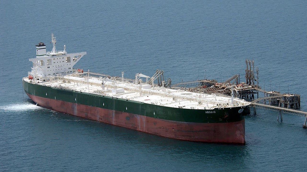
Oil tanker equipment arrangement brings together cargo-deck systems, engine-room layout, fire protection, safe access, and maintenance planning. This guide distinguishes requirements cited from Bureau Veritas NR467, July 2026, from typical arrangements and engineering recommendations.
Key Takeaways
- Tanker arrangement design should begin with the functional segregation of the cargo area, machinery spaces, accommodation block, and mooring stations.
- Every mandatory statement in this article is linked to a specific provision of the July 2026 edition of Bureau Veritas NR467.
- Common layouts—such as locating the cargo manifold near the mid-length of the cargo deck or installing the main engine on the centerline—are not automatically explicit BV requirements; they are identified here as Typical Arrangements.
- Numerical minima are valid only within their stated scope. For example, the 600 mm and 750 mm boiler clearances apply only when the double bottom below the boiler is capable of carrying fuel oil.
- Compliance with minimum class requirements does not replace a maintainability review, component-removal planning, interface coordination, emergency-access assessment, or lifecycle-cost analysis.
1. Method Used to Distinguish Requirements from Recommendations
To avoid confusing rule requirements with design judgement, four labels are used throughout this article.
Regulatory Requirement
A provision expressed in the rules by terms such as “shall”, “is to”, “are to”, or “is not to”. A non-compliant arrangement normally requires formal acceptance by the classification society or approval of an equivalent arrangement.
Typical Arrangement
A layout commonly found on conventional tankers but not necessarily prescribed as mandatory by the cited rule provision.
Engineering Recommendation
A proposal intended to improve safety, operability, maintainability, or lifecycle performance. It must not be presented as a statutory or class minimum.
Author’s Interpretation
An analytical conclusion obtained by reading several requirements and design considerations together, although the conclusion is not stated verbatim in the rules.
When interpreting BV text, terms such as “recommended”, “preferably”, and “should” are treated as guidance or preference rather than as absolute mandatory language.
The editorial and source-selection principles applied to this guide are described in the Ocean Tech Review Editorial Policy.
2. Scope and Regulatory Basis
This article addresses the arrangement of a conventional oil tanker with the following general characteristics:
- an aft machinery space;
- a cargo-tank block amidships;
- an aft superstructure and accommodation block located abaft the cargo area;
- deck-mounted cargo piping and cargo-transfer equipment;
- anchoring and mooring stations at the forward and aft ends.
The principal references are:
- BV NR467 Part B — Hull and Stability;
- BV NR467 Part C — Machinery, Electricity, Automation and Fire Protection;
- BV NR467 Part D — Service Notations.
Page numbers cited in this article are the printed page numbers shown inside the rule books, not the page numbers displayed by PDF-reading software.
Audit limitation: SOLAS and MARPOL are mentioned only where the BV rules themselves refer to them. The primary texts of SOLAS, MARPOL, ISGOTT, and OCIMF guidance were not independently audited for this version.
The article must therefore not be treated as a complete comparison of all regulatory regimes.
3. Audit of Critical Numerical Requirements
3.1 Cargo-Tank Access Openings
| Item | Minimum / Provision | Exact BV Reference | Scope of Application |
|---|---|---|---|
| Horizontal opening | At least 600 × 600 mm | BV NR467 Part D, Ch. 7, Sec. 2, Art. 2.2.3(b), p. 154 | Access to cargo-area spaces on oil tankers and applicable FLS tankers. |
| Vertical opening | At least 600 × 800 mm | BV NR467 Part D, Ch. 7, Sec. 2, Art. 2.2.3(c), p. 154 | Openings in swash bulkheads, floors, girders, and web frames; the lower edge is to be no more than 600 mm above the bottom unless footholds are provided. |
| Exception | Smaller dimensions may be accepted | BV NR467 Part D, Ch. 7, Sec. 2, Art. 2.2.3(d), p. 155 | Only for tankers below 5,000 DWT, subject to demonstrating personnel passage and casualty removal and to Society acceptance. |
BV explicitly specifies 600 × 600 mm and 600 × 800 mm openings. For tankers below 5,000 DWT, however, smaller openings may be accepted in defined circumstances and with Society approval.
3.2 Safe Access to the Forecastle
| Item | Requirement | Reference |
|---|---|---|
| Clear width of walkway or gangway | At least 1 m | Part D, Ch. 7, Sec. 2, Art. 2.2.6(a), p. 155 |
| Spacing of access openings | Not more than 40 m | Art. 2.2.6(d) |
| Threshold for shelters | Exposed deck length exceeding 70 m | Art. 2.2.6(e) |
| Spacing of shelters | Not more than 45 m | Art. 2.2.6(e) |
The requirement applies to oil tankers generally, and the route is to provide safe access to the forecastle even in severe weather conditions.
3.3 Cargo Pump-Room Ventilation and Gas Detection
| Item | Requirement | Exact Reference |
|---|---|---|
| Ventilation rate | At least 20 air changes per hour | Part D, Ch. 7, Sec. 4, Art. 3.5.1(a), p. 187 |
| Ventilation through the upper inlet when the lower inlet is closed | At least 15 air changes per hour | Art. 3.5.1(e) |
| Approximate elevation of emergency inlet | About 2 m above the lower grating | Art. 3.5.1(c) |
| Hydrocarbon alarm threshold | Not more than 10% LFL | Art. 3.5.2(c), p. 188 |
The cargo pump-room is to be ventilated by extraction using a non-sparking fan.
The alarm threshold is not to exceed 10% of the lower flammable limit, and alarms are to be provided in the pump-room, engine control room, cargo control room, and navigation bridge.
Applicability condition: the explosion-protection provisions of Article 3.5.2 generally do not apply to the service notations “oil tanker, flash point > 60°C”, “oil tanker, asphalt carrier”, and “FLS tanker, flash point > 60°C”, unless the cargo is carried at a temperature not more than 15°C below its flash point.
3.4 Cargo-Tank Vent Outlets
| Outlet Type | Minimum Height | Minimum Horizontal Separation | Velocity Requirement |
|---|---|---|---|
| Free-flow vent | 6 m | 10 m | No fixed 30 m/s requirement |
| High-velocity vent | 2 m | 10 m | At least 30 m/s |
The 10 m separation is measured from the nearest air intake, opening into a space containing an ignition source, deck machinery, or other equipment presenting an ignition hazard. Vapour discharge is to be vertically upwards.
Venting capacity is also to be based on the maximum design loading rate multiplied by at least 1.25.
Source: BV NR467 Part D, Ch. 7, Sec. 4, Art. 4.2.6, p. 190.
3.5 Deadweight Threshold for Inert Gas
| Condition | Requirement |
|---|---|
| Oil tanker or FLS tanker with DWT ≥ 8,000 | Inert-gas system or accepted equivalent arrangement. |
| 8,000 ≤ DWT < 20,000 | BV may accept an equivalent arrangement. |
| Tanker fitted for crude-oil washing | Inert-gas system required irrespective of the above threshold. |
| System coverage | All cargo tanks and slop tanks. |
Source: BV NR467 Part D, Ch. 7, Sec. 6, Arts. 5.1.1 and 5.1.2, pp. 208–209.
3.6 Boiler Clearances
| Clearance | Requirement | Applicability Condition |
|---|---|---|
| Boiler to vertical boundary | At least 450 mm | In all cases covered by the provision, in addition to adequate inspection space. |
| Cylindrical boiler to the double-bottom tank top | At least 600 mm | Only when the double bottom below the boiler is capable of carrying fuel oil. |
| Water-tube boiler to the tank top | At least 750 mm | Same condition. |
| Vertical-tube boiler above a non-fuel double bottom | May be reduced to 200 mm | Subject to the specific provision. |
Source: BV NR467 Part C, Ch. 1, Sec. 3, Arts. 8.2.2–8.2.4, p. 130.
3.7 Machinery-Space Escape Routes
| Item | Requirement |
|---|---|
| Internal dimensions of protected enclosure | At least 800 × 800 mm |
| Clear width of inclined stairway or ladder | At least 600 mm |
| Maximum inclination | 60° |
| Number of escape routes from a Category A machinery space | Two, except where the specific provision allows otherwise |
4. Oil Tanker Equipment Arrangement Principles
4.1 Segregation of the Cargo Area and Machinery Spaces
Regulatory Requirement
For ships assigned the service notations “oil tanker” or “FLS tanker” and falling within Part D, Chapter 7, Section 2, Articles 2.1.2–2.1.5:
- the cargo pump-room is to be separated from other spaces by oil-tight bulkheads;
- direct access between the cargo pump-room and machinery spaces is not permitted;
- the cargo pump-room, cargo tanks, slop tanks, and cofferdams are to be located forward of the machinery spaces;
- cargo tanks and slop tanks are to be separated from the machinery spaces by a cofferdam, cargo pump-room, fuel-oil tank, or ballast tank.
Source: BV NR467 Part D, Ch. 7, Sec. 2, Arts. 2.1.3–2.1.4, p. 152.
Section 2 applies to several service notations, but Articles 2.1.2–2.1.5 are specific to “oil tanker” and “FLS tanker”.
Ships carrying cargoes with flash points above 60°C, asphalt carriers, and certain FLS tankers are subject to the alternative arrangements in Article 2.1.6.
Typical Arrangement
A conventional tanker commonly has the following longitudinal sequence:
- forepeak and forward mooring station;
- cargo-tank block;
- cargo pump-room or another separating space;
- machinery spaces;
- aft superstructure and accommodation block.
This sequence is a logical outcome of the segregation requirements. BV does not require every tanker to have an identical general arrangement, and ships with machinery spaces located elsewhere are subject to special consideration.
Author’s Interpretation
The boundary between the cargo area and machinery spaces should not be treated merely as a bulkhead line on the general-arrangement drawing. It must also be maintained in:
- piping;
- cable routing;
- ventilation ducting;
- drainage;
- hazardous-area classification;
- fire control;
- personnel access.
4.2 Accommodation Spaces and External Openings
Regulatory Requirement
Accommodation spaces, main cargo control stations, other control stations, and service spaces are generally to be located abaft the cargo tanks, slop tanks, and separating spaces.
The arrangement is to prevent a single failure of a deck or bulkhead from allowing cargo gas or vapour to enter those spaces.
Source: BV NR467 Part D, Ch. 7, Sec. 2, Art. 2.1.5(a), p. 152.
Doors, air inlets, air outlets, and other openings serving accommodation spaces, service spaces, control stations, and machinery spaces are not to face the cargo area. They are to be located either:
- on a transverse bulkhead facing away from the cargo area; or
- on the outboard side of the superstructure.
The minimum distance is 4% of the ship’s length but not less than 3 m; a distance greater than 5 m need not be required.
Machinery-space air inlets and outlets should be located as far aft as practicable and outside this zone.
Source: BV NR467 Part D, Ch. 7, Sec. 2, Art. 2.2.2(a) and (d), p. 154.
Engineering Recommendation
Geometric separation alone is not sufficient. The arrangement study should also consider:
- airflow over the superstructure;
- possible re-entrainment of cargo vapour;
- the location of the funnel and exhaust outlets;
- ballast and laden conditions;
- stern-loading operations, where fitted;
- the likely path of a vapour cloud following a release.
4.3 Control of Deck Spillage
Regulatory Requirement
A continuous coaming at least 300 mm high may be fitted across the ship to keep deck spillage away from accommodation and service spaces.
Source: BV NR467 Part D, Ch. 7, Sec. 2, Art. 2.1.5(d), p. 153.
Gutter bars in the cargo-manifold region that exceed 300 mm in height are to be treated as bulwarks and provided with suitable freeing ports. The free-surface effect of retained liquid may also require a stability assessment.
Source: BV NR467 Part D, Ch. 7, Sec. 2, Art. 3.7, pp. 160–161.
Engineering Recommendation
Drip trays and gutter bars should not be sized only for the owner’s nominal spill volume. The review should also address the drainage route, scupper closure during cargo transfer, rainfall, green water, cleaning access, and the risk of crew slipping.
5. Cargo-Deck Equipment Arrangement
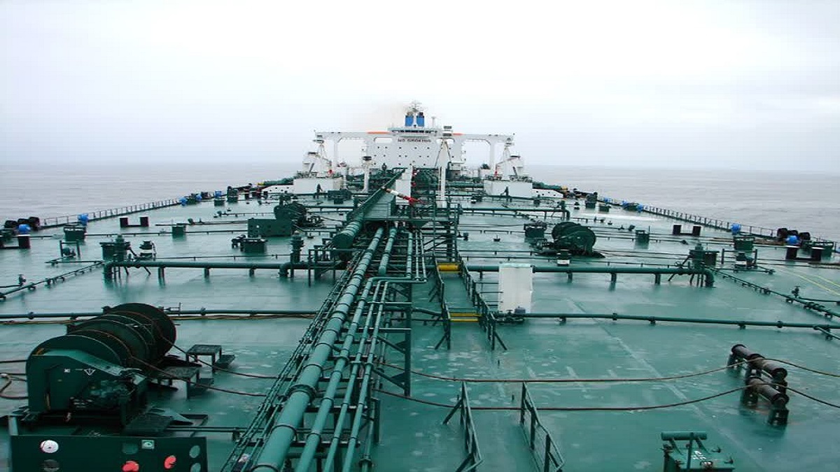
A practical oil tanker equipment arrangement must preserve safe access to cargo piping, manifolds, valves, venting systems, and emergency equipment.
5.1 Cargo Manifold
Regulatory Requirement
BV requires that:
- each cargo tank can be isolated by a stop valve;
- shut-off valves are fitted at both ends of the cargo manifold;
- main valves located below the pump-room grating can be remotely operated from above the floor level.
Source: BV NR467 Part D, Ch. 7, Sec. 4, Art. 3.4.3, p. 186.
Typical Arrangement
On many tankers, the cargo manifold is arranged near the mid-length of the cargo deck on both sides of the vessel. This commonly:
- facilitates connection to shore loading arms;
- keeps average cargo-line lengths within a practical range;
- allows the use of a hose-handling crane;
- provides a practical relationship with the cargo control room.
This location is not an explicit BV requirement and must be checked against the dimensional and operating envelopes of the intended terminals.
Engineering Recommendation
A dedicated working envelope should be maintained around the cargo manifold for:
- breaking and making flange connections;
- installing reducers and blank flanges;
- spill containment;
- sampling;
- access to emergency shutdown controls;
- earthing or bonding connections;
- hose-crane movement;
- safe personnel positioning away from pressure-release and spray paths.
The principal crew walkway should not pass through a credible spill zone or directly in front of pressurised flanges.
5.2 Cargo Piping
Regulatory Requirement
The complete pumping and piping system used for cargo transfer is to be independent of other ship systems and, except for permitted arrangements such as bow or stern loading stations, is not to extend outside the cargo area.
Source: BV NR467 Part D, Ch. 7, Sec. 4, Art. 3.1.1, p. 183.
Cargo piping—including vent lines, relief-valve discharge lines, and gas-freeing lines—is generally to remain within the cargo area. Where routing outside the cargo area is accepted, the piping is not to pass through tanks or enclosed spaces.
Passage through ballast tanks is permitted only for short lengths and under reinforced construction conditions.
Source: BV NR467 Part D, Ch. 7, Sec. 4, Art. 3.4.1, p. 185.
At a bulkhead penetration:
- excessive stress is not to be transferred to the bulkhead;
- a bolted flange is not permitted within the bulkhead.
To control electrostatic charging, the loading pipe is to be led as low as practicable into the cargo tank, and piping components are to be electrically continuous with one another and with the hull.
This requirement does not apply to certain high-flash-point tankers or asphalt carriers.
Source: BV NR467 Part D, Ch. 7, Sec. 4, Arts. 3.4.2–3.4.4, p. 186.
Engineering Recommendation
A cargo-piping route study should simultaneously review:
- required gradients for drainage and stripping;
- dead legs;
- thermal expansion;
- relative movement between deck structure and tanks;
- clearance for valve and strainer dismantling;
- pipe-support loads;
- interference with walkways;
- tank washing and gas-freeing capability;
- access for non-destructive examination of critical welds.
Author’s Interpretation
The shortest pipe route is not always the best route. A slightly longer line with better drainage, regular support spacing, and improved maintenance access may provide better lifecycle performance.
5.3 Bilge and Ballast Systems within the Cargo Area
Regulatory Requirement
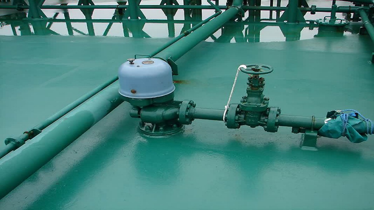
Bilge, ballast, and scupper systems serving spaces within the cargo area are to be independent of systems outside the cargo area and are generally not to extend beyond that area.
Fuel-oil systems are to be independent of cargo piping and are not to connect to cargo tanks or slop tanks.
Source: BV NR467 Part D, Ch. 7, Sec. 4, Art. 2.1.2, pp. 177–178.
At least one bilge pump is required for spaces within the cargo area and is to be installed in the cargo pump-room or another suitable space within the cargo area.
Pump-room bilge discharge is to be controllable from outside and is to be provided with a high-level alarm.
Segregated ballast tanks are required for crude-oil tankers of 20,000 DWT and above and product carriers of 30,000 DWT and above. The ballast system serving these tanks is to be separate from cargo-oil and fuel-oil systems.
Engineering Recommendation
An emergency cargo–ballast interconnection should not appear in the three-dimensional model as an ordinary cross-connection. The shut-off valve, non-return valve, removable spool piece, warning marking, and operator access should be obvious and auditable.
5.4 Cargo Pumps and Cargo Pump-Room
Regulatory Requirement
Each cargo tank is to be provided with at least two fixed and separate means of discharge and stripping. For a tank fitted with an independent submerged pump, the second means may be portable.
Cargo pumps may be installed:
- in a dedicated cargo pump-room;
- on the open deck;
- inside a cargo tank, subject to an approved design.
Source: BV NR467 Part D, Ch. 7, Sec. 4, Art. 3.2.1, p. 183.
The cargo-pump prime mover is not to be located within the cargo area except for specified arrangements, including:
- a steam drive with steam temperature not exceeding 220°C;
- a hydraulic motor;
- an electric motor complying with the applicable electrical requirements.
A cargo pump with an electric motor submerged in a cargo tank is not permitted. Cargo pumps are also to be capable of being stopped both from outside the pump-room and from a position close to the pump.
Source: BV NR467 Part D, Ch. 7, Sec. 4, Arts. 3.2.3 and 3.2.6, p. 184.
Regulatory Requirement
The cargo pump-room is to:
- have mechanical exhaust ventilation;
- provide at least 20 air changes per hour;
- use non-sparking fans;
- extract air near the bilges and lower parts of the space;
- have an emergency air inlet about 2 m above the lower grating.
Continuous hydrocarbon monitoring with an alarm threshold not exceeding 10% LFL is also required.
Typical Arrangement
Three commonly used cargo-pumping architectures are:
- central cargo pump-room;
- deepwell pump system;
- individual submerged or hydraulically driven pump arrangement.
Selection depends on cargo type, tank subdivision, discharge rate, maintenance strategy, and owner policy. BV does not mandate a single pumping architecture.
Engineering Recommendation
A cargo pump-room arrangement should provide not only installation space, but also clear routes for:
- removal of the pump shaft or casing;
- coupling dismantling;
- access to seals and bearings;
- movement of personnel wearing protective clothing and breathing apparatus;
- access to gas detectors;
- bilge drainage;
- escape following a leak or fire.
5.5 Cargo-Tank Venting
Regulatory Requirement
The cargo-tank venting system is to be completely separate from the air pipes of other shipboard spaces. Vent openings are to be located to minimize the possibility of flammable vapor entering spaces containing ignition sources or accumulating around deck equipment.
For outlets covered by Part D, Chapter 7, Section 4, Article 4.2.6:
- vapour is to be discharged vertically upwards;
- a free-flow outlet is to terminate at least 6 m above the cargo-tank deck;
- a high-velocity outlet is to terminate at least 2 m above the cargo-tank deck;
- the horizontal distance from air intakes, openings into spaces containing ignition sources, and hazardous deck equipment is to be at least 10 m;
- for a high-velocity outlet, the discharge velocity is not to be less than 30 m/s.
A pressure/vacuum valve is to be accessible and provided with means for manual opening and locking in the open position. It is not to be capable of being locked closed.
Engineering Recommendation
In addition to minimum separation distances, a CFD or dispersion assessment should consider:
- the superstructure wind shadow;
- funnel wake;
- changes in wind direction while alongside;
- personnel at mooring stations;
- doors that may be open during operations;
- pressure/vacuum valve maintenance;
- icing, blockage, and contamination risks.
5.6 Inert-Gas System
Regulatory Requirement
An oil tanker or FLS tanker of 8,000 DWT and above is to be fitted with an inert-gas system or an accepted equivalent arrangement. For ships from 8,000 DWT to below 20,000 DWT, BV may accept an equivalent system.
Every tanker fitted for crude-oil washing is also to have an inert-gas system. The system is to cover all cargo tanks and slop tanks.
Source: BV NR467 Part D, Ch. 7, Sec. 6, Arts. 5.1.1–5.1.2, pp. 208–209.
Double-hull spaces adjacent to cargo tanks are also to be capable of connection to inert gas. Where a permanent connection is provided, arrangements are required to prevent hydrocarbons from passing from the cargo tank into those spaces.
Typical Arrangement
A conventional inert-gas system may include the following functional sequence:
- inert-gas source or nitrogen generator;
- scrubber, where used;
- blower;
- deck water seal;
- non-return device;
- inert-gas main;
- tank branch lines;
- oxygen analyser;
- pressure-control equipment.
Engineering Recommendation
The deck seal, non-return device, and instruments should be located so that:
- inspection access is available;
- they are protected from cargo-operation impact;
- their drainage is visible;
- maintenance does not obstruct the principal deck route;
- off-specification gas is not discharged toward an air intake.
5.7 Cargo-Deck Fire Protection
Regulatory Requirement
For tankers required to have a fixed deck foam system:
- a foam monitor and foam-applicator hose connection are to be installed on both port and starboard sides, forward of the poop or accommodation spaces and facing the cargo-tank deck;
- at least four foam applicators are required;
- the outlet arrangement is to permit foam from at least two applicators to reach every part of the cargo-tank deck;
- the main control station is to be outside the cargo area, adjacent to the accommodation block, and accessible during a fire.
Source: BV NR467 Part D, Ch. 7, Sec. 6, Arts. 3.3.1–3.3.4, pp. 207–208.
The capacity of each foam applicator is not to be less than 400 L/min, and its throw in still air is not to be less than 15 m.
The maximum distance from a foam monitor to the farthest end of the protected area is not to exceed 75% of the monitor throw.
In the tanker fire main, isolation valves are to be fitted at the forward end of the poop in a protected position and subsequently at intervals not exceeding 40 m along the cargo-tank deck.
Engineering Recommendation
Foam coverage should not be checked only in plan view. The three-dimensional model should identify obstruction by:
- pipe racks;
- crane pedestals;
- vent risers;
- raised walkways;
- manifold structures;
- temporary cargo-operation equipment.
6. Anchoring, Towing, and Mooring Equipment
6.1 Anchoring Equipment
Regulatory RequirementThe hawse pipe is to have adequate strength, and its position and inclination are to facilitate lowering and heaving the anchor while preventing damage to the hull.
The chain locker is to:
- have sufficient capacity for the full chain;
- be divided into two compartments where two chains are fitted;
- permit the inboard end of the chain to be released from outside the chain locker;
- have watertight boundaries and access openings, together with suitable drainage.
Source: BV NR467 Part B, Ch. 12, Sec. 4, Arts. 2.4 and 2.7, pp. 553–554.
Engineering Recommendation
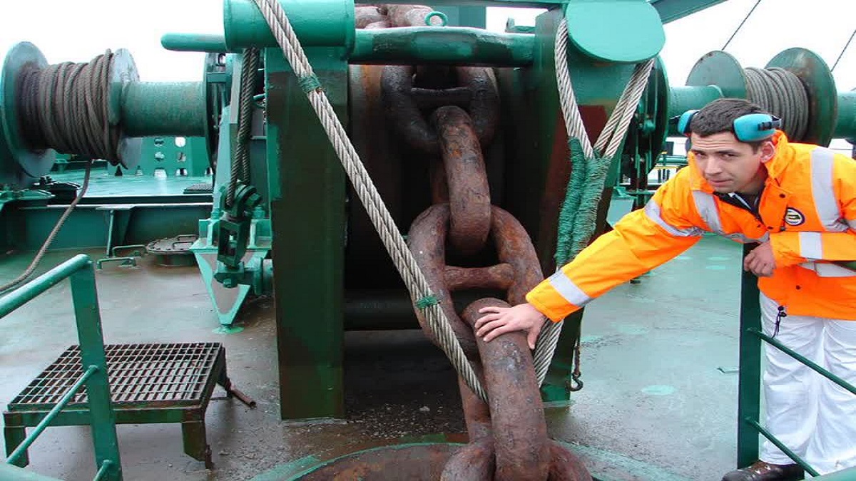
The windlass arrangement should provide maintenance space for:
- brake equipment;
- gearbox;
- hydraulic motor;
- chain stopper;
- bearings;
- foundation bolts.
The heavy-component removal route should not be blocked by the bulwark or mooring fittings.
6.2 Emergency Towing Arrangement
Regulatory Requirement
Under BV Part B, Chapter 12, Section 4, Article 3.1.2, ships of 20,000 DWT and above with specified service notations—including “oil tanker ESP” and “FLS tanker”—are subject to the following:
- an emergency towing arrangement is to be fitted at both ends of the vessel;
- the additional class notation ETA is mandatory;
- the system is to be capable of rapid deployment and connection to a tug without main power.
This requirement should not be generalised to every tanker without checking the applicable service notation.
The fairlead is to accommodate towing directions up to 90° to port and starboard and 30° downward.
It is to be installed as close as practicable to the deck and the centreline, while the chafing chain should run approximately parallel to the deck.
6.3 Mooring Arrangement
Typical Arrangement
Appendix 2 of Part B, Chapter 12 explicitly identifies its provisions as guidance rather than conditions of classification. The following points should therefore not be described as absolute class requirements.
The guidance recommends that:
- interference between towing and mooring lines is avoided as far as practicable;
- towing fittings are independent from mooring fittings;
- the mooring line lead from the winch drum to the fairlead is as direct as practicable;
- a suitable contact radius is provided at changes in direction to reduce rope wear;
- a closed chock is preferred for towing;
- the associated bitt or bollard is slightly offset from the chock and located at least 2 m away;
- the warping drum is preferably not more than 20 m from the chock.
Engineering Recommendation
The final mooring arrangement should be reviewed against:
- the intended terminals;
- shore-fairlead elevations;
- the operating draught range;
- line minimum breaking load and material;
- brake holding capacity;
- line-lead direction;
- operator field of view;
- snap-back or rope-recoil risk;
- emergency escape routes.
BV also places responsibility on the designer to verify that the line selection and arrangement are suitable for the expected shore equipment and environmental design conditions.
7. Machinery-Space Arrangement
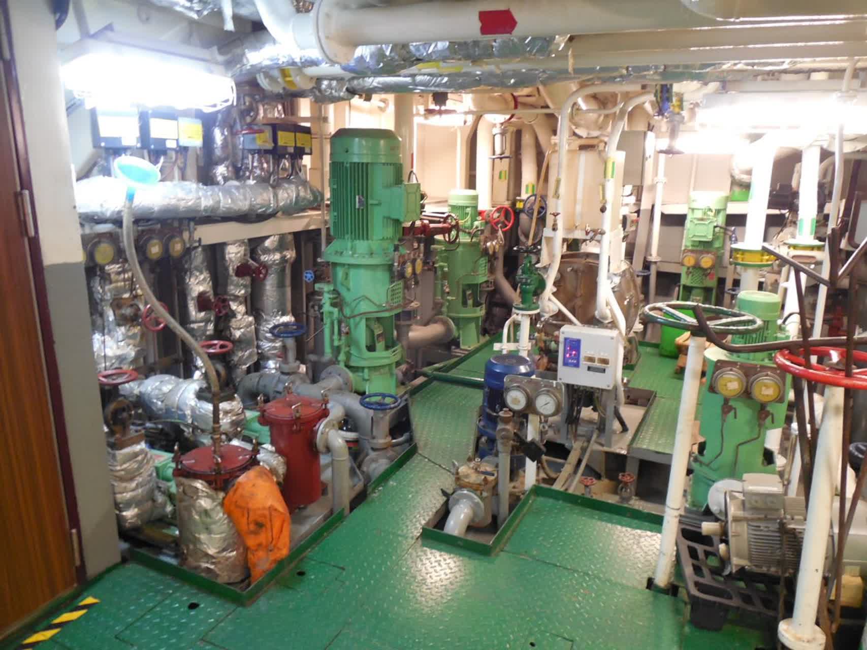
Within the machinery space, oil tanker equipment arrangement should account for maintenance access, lifting routes, structural foundations, ventilation, and fire protection.
7.1 Watertight Boundaries and Shaft Tunnel
Regulatory Requirement
The machinery space is to be separated from cargo and accommodation spaces at the forward and aft ends by watertight bulkheads extending to the freeboard deck.
The stern tube is also to be enclosed within a watertight space of restricted volume.
Source: BV NR467 Part B, Ch. 2, Sec. 1, Art. 4.1, p. 64.
The shaft tunnel is to be watertight and large enough to provide ready access to the shafting. Its entrance is to be through a watertight door in the aft machinery-space bulkhead.
Source: BV NR467 Part B, Ch. 2, Secs. 2 and 3, pp. 71 and 75.
7.2 Main Engine, Thrust Block, and Foundations
Regulatory Requirement
All machinery and shafting are to be secured so that loads are properly transmitted to the ship’s structure, and adjacent structure is to be reinforced.
Abrupt changes in structural system between the machinery space and adjacent hull structure are to be avoided.
The foundations of the following items are to maintain the necessary stiffness and alignment in all loading conditions:
- main propulsion unit;
- reduction gear;
- shaft bearings;
- thrust bearing.
Source: BV NR467 Part B, Ch. 11, Sec. 2, Arts. 2.1.1–2.1.8, p. 428.
In a longitudinally framed double bottom:
- plate floors are to be fitted at every frame under the main engine and thrust bearing;
- where the engine or thrust bearing is bolted directly to the inner bottom, the net inner-bottom thickness is to be at least 19 mm;
- hold-down bolts are to be located as close as practicable to floors and longitudinal girders;
- direct installation of heavy equipment on the inner bottom requires suitable increases in floor and girder thickness.
Source: BV NR467 Part B, Ch. 11, Sec. 2, Arts. 2.2.8–2.2.12, p. 430.
Typical Arrangement
On a conventional single-screw ship, the main engine is normally arranged on the centreline and in the longitudinal direction to maintain a direct relationship with the shaft line.
This is common practice; the cited provisions do not state a universal rule that every main engine must be on the centerline.
Engineering Recommendation
Before decks and platforms are frozen, a three-dimensional maintenance envelope should be prepared for removal of:
- pistons;
- cylinder heads;
- liners;
- turbocharger rotors;
- main bearings;
- fuel pumps;
- exhaust valves;
- thrust-bearing components.
The handling route from the dismantling position to the workshop or deck opening should be continuous and unobstructed.
7.3 Platforms and Double-Bottom Structure
Regulatory Requirement
Within the machinery space:
- the number of side bottom girders is to be increased as necessary to provide adequate stiffness;
- their spacing is generally not to exceed three times the longitudinal spacing and is in no case to exceed 3 m;
- girders below the main machinery seating are to extend through the full length of the machinery space.
Typical Arrangement
BV uses the term “preferably” when recommending that machinery-space platforms continue, as far as practicable, the longitudinal members, platforms, and side girders of adjacent regions. This is a structural preference rather than an absolute requirement for every arrangement.
7.4 Fuel-Oil Tanks
Regulatory Requirement
As far as practicable, fuel-oil tanks are to:
- form part of the ship’s structure;
- be located outside Category A machinery spaces.
Where a fuel-oil tank other than a double-bottom tank must be located within or adjacent to a Category A machinery space:
- at least one vertical side is to be contiguous with the machinery-space boundary;
- the common boundary with the machinery space is to be minimised;
- a tank within the space is not to contain fuel with a flash point below 60°C.
A fuel tank is also not to be positioned where leakage may fall onto a hot surface or directly above a boiler or another high-temperature location.
Source: BV NR467 Part B, Ch. 2, Sec. 2, Art. 8.1, p. 72.
Part C repeats these principles and states a general 450 mm clearance between a fuel tank and a boiler.
The 600 mm and 750 mm clearances are conditional upon the double bottom below the boiler being capable of carrying fuel oil.
Engineering Recommendation
Around settling and service tanks, the following scenarios should be reviewed:
- gauge-glass failure;
- valve or flange leakage;
- overflow;
- operation of quick-closing valves;
- access to remote shutdowns;
- liquid flow across platforms;
- contact with exhaust piping or turbochargers.
7.5 Boilers and Thermal Equipment
Regulatory Requirement
The clearance from a boiler to a vertical boundary is not to be less than 450 mm, and sufficient space is to be provided for inspection and maintenance of adjacent structure.
Where the double bottom below the boiler is capable of carrying fuel oil:
- the clearance below a cylindrical boiler is to be at least 600 mm;
- the clearance below a water-tube boiler is to be at least 750 mm.
Installation of an oil tank in the space above the boiler is not permitted.
Source: BV NR467 Part C, Ch. 1, Sec. 3, Arts. 8.2.2–8.2.4, p. 130.
Engineering Recommendation
In addition to the numerical clearances, the layout should be checked for burner inspection, tube withdrawal, soot removal, safety-valve access, and burner-assembly removal.
7.6 Pumps, Purifiers, and Flammable-Fluid Equipment
Regulatory Requirement
Spaces containing settling tanks, fuel-oil service tanks, or oil-consuming installations are to be readily accessible and adequately ventilated. Where flammable-fluid leakage may occur during normal operation or maintenance, arrangements are to prevent the leakage from reaching ignition hazards.
BV generally recommends that the principal components of flammable-fluid preparation systems, including purifiers, be installed in a separate room having steel boundaries, a self-closing door, ventilation, fire detection, and fire extinguishing.
Alternative arrangements using shielding, drip trays, and local exhaust may also be accepted.
Source: BV NR467 Part C, Ch. 4, Sec. 6, Art. 4.1, pp. 697–698.
Engineering Recommendation
Components serving the same system may be grouped to reduce piping length, but redundant items should not be positioned so that a single leak, fire, or falling component can disable both simultaneously.
7.7 Main and Emergency Generating Stations
Regulatory Requirement
The main generating station is to be located within the machinery spaces and between the main transverse watertight bulkheads.
The main switchboard is to be installed as close as practicable to the main generating station, in the same machinery space, and within the same A-60 boundary in the horizontal and vertical directions.
Source: BV NR467 Part C, Ch. 2, Sec. 11, Art. 2.2, p. 567.
The emergency source of electrical power, emergency switchboard, and associated equipment are to:
- be located above the uppermost continuous deck;
- be readily accessible from the open deck;
- not be located forward of the collision bulkhead;
- generally not be contiguous with a Category A machinery space or the main source of electrical power;
- have an A-60 boundary where unavoidable adjacency occurs.
The emergency battery is generally not to be installed in the same space as the emergency switchboard.
Source: BV NR467 Part C, Ch. 2, Sec. 11, Arts. 3.1–3.4, p. 568.
Engineering Recommendation
The diesel-generator arrangement should be checked for:
- rotor or alternator removal;
- cylinder-head dismantling space;
- exhaust routing;
- combustion-air supply;
- separation of power and control cables;
- vibration transmission;
- access to the local emergency stop.
7.8 Switchboards, Batteries, and Cable Routes
Regulatory Requirement
An unobstructed working space is to be provided in front of the main switchboard; BV indicates that this is generally about 1 m.
Where maintenance access is required behind the switchboard, the passage is generally not to be less than 0.6 m wide.
Pipes and conduits are not to be installed directly above the switchboard unless fully welded or otherwise protected against spray and dripping.
Source: BV NR467 Part C, Ch. 2, Sec. 12, Art. 6.1, p. 576.
Cable runs for emergency and essential services are to be kept, as far as practicable, away from Category A machinery spaces and high fire-risk areas.
Duplicate feeders are to follow different routes and be separated as far as practicable in both horizontal and vertical directions.
Batteries are to be protected against heat, cold, spray, steam, and other harmful conditions, and the battery space is to be ventilated. Starting batteries are to be located as close as practicable to the associated engine.
A vented battery installation with charging power above 2 kW is to be placed in a dedicated battery room or a suitable deck locker with mechanical exhaust ventilation.
7.9 Machinery-Space Fire Protection
Regulatory Requirement
A Category A machinery space containing internal-combustion machinery is to be protected by an approved fixed fire-extinguishing system.
Portable extinguishers are to be distributed so that:
- the walking distance from any point to an extinguisher does not exceed 10 m;
- at least two extinguishers are provided in the space.
For smaller cargo-ship machinery spaces, BV may consider a reduction under the applicable provision.
Source: BV NR467 Part C, Ch. 4, Sec. 6, Art. 4.3, p. 698.
For cargo ships of at least 2,000 GT and Category A machinery spaces exceeding 500 m³, a fixed local application system is required in addition to the main fixed extinguishing system.
It is to cover fire-hazard areas of the engines, the boiler front, incinerator, and heated-fuel purifiers.
Source: BV NR467 Part C, Ch. 4, Sec. 6, Art. 4.7, p. 699.
7.10 Means of Escape
Regulatory Requirement
On a cargo ship, a Category A machinery space is generally to have two separate means of escape. One accepted arrangement consists of two steel ladders positioned as far apart as practicable, one of which is within a protected enclosure.
The protected enclosure is to:
- have internal dimensions of at least 800 × 800 mm;
- be provided with emergency lighting.
An inclined ladder or stairway forming part of the escape route outside the protected enclosure is to:
- be of steel construction;
- have steel shielding beneath it;
- have an inclination not exceeding 60°;
- have a clear width of at least 600 mm.
For a ship below 1,000 GT, BV may permit one escape route to be dispensed with under the conditions stated in the rule.
Source: BV NR467 Part C, Ch. 4, Sec. 8, Art. 2.3.4, pp. 708–709.
Engineering Recommendation
The final escape-route model should be reviewed with all equipment installed, not only on an empty general-arrangement drawing. The following items are not to reduce the required clear width or height:
- valve handwheels;
- cable trays;
- temporary storage;
- equipment doors in the open position;
- handrails;
- spare parts;
- pipe supports;
- insulation.
8. Interfaces Between the Cargo Deck and Machinery Spaces
Regulatory Requirement
Fuel-oil systems are to be independent of cargo piping and are not to connect to cargo tanks or slop tanks. Bilge, ballast, and scupper systems within the cargo area are likewise to remain independent from systems outside the cargo area.
For tankers of 600 DWT and above, ballast lines passing through cargo tanks are not permitted except for short lengths complying with reinforced construction requirements.
Sliding couplings are not permitted for expansion compensation in such locations; expansion bends are to be used.
Author’s Interpretation
A useful test of the cargo-deck/machinery-space interface is the following question:
Could failure of a valve, pipe, cable, fan, or boundary transfer a cargo-area hazard into a safe space or the machinery space?
If the answer is yes, effective system independence has not yet been achieved—even if the two systems appear in different colours on the piping and instrumentation diagram.
9. Common Arrangement Errors
The items in this section are not independent rule requirements. They are engineering conclusions drawn from the cited provisions and recurring design problems.
Engineering Recommendation
1. Adequate space is provided to install the main engine, but no piston-removal route exists.
2. A valve appears accessible on the P&ID but is located behind a pipe rack in the three-dimensional model.
3. A vent outlet meets the minimum geometric distance but is located within the superstructure wind shadow.
4. The cargo manifold interrupts the principal crew walkway.
5. A drip tray has no effective drainage or overflows during rainfall.
6. A mooring line passes over equipment, a handrail, or an escape route.
7. The winch control position is located within a probable rope-recoil path.
8. Redundant pumps are adjacent and exposed to the same fire.
9. The emergency cable run follows the same hazard zone as the main feeder.
10. Liquid piping is installed above a switchboard.
11. The equipment foundation is not aligned with the floors and girders below.
12. A foam monitor has suitable plan-view coverage, but a pipe rack blocks its discharge field.
13. An escape route loses adequate width after insulation and cable trays are installed.
14. The boiler location is incompatible with tube withdrawal or burner maintenance.
15. Gas-detector positions are selected only on a regular grid, while low-airflow pockets are ignored.
10. Final Design Checklist
Cargo-Deck Checklist
Engine-Room Checklist
11. Conclusion
Effective oil tanker equipment arrangement requires more than compliance with minimum class-rule dimensions.
A successful tanker arrangement is not produced by placing equipment in whatever space remains. From the earliest design stage, four subjects must be coordinated simultaneously:
1. regulatory compliance;
2. operational safety;
3. maintainability;
4. proper transmission of equipment loads into the hull structure.
Classification rules define minima such as walkway width, vent separation, ventilation rate, or the number of escape routes. They do not necessarily determine the optimum position of every pump, platform, valve, or maintenance space for a specific vessel.
Author’s Interpretation
The most expensive arrangement error is usually not a shortage of a few centimetres; it is a lack of coordination between disciplines. Late relocation of a pump or winch may simultaneously affect:
- foundations;
- pipe supports;
- cable trays;
- ventilation;
- drainage;
- the fire-control plan;
- access routes.
Maintainability and interface management should therefore be incorporated before the general arrangement and three-dimensional model are frozen. Compliance with minimum class requirements is necessary, but it is not sufficient to achieve a safe, operable, and lifecycle-efficient ship.
Further classification-rule analyses and technical literature assessments are available in the Ocean Tech Review Research Reviews section.
12. Register of Principal Regulatory Sources
Bureau Veritas. NR467 Rules for the Classification of Steel Ships, July 2026.
Bureau Veritas — Part B
Open the official NR467 catalogue for Part B (July 2026)
Document: Rules for the Classification of Steel Ships, NR467
Part: B — Hull and Stability
Edition: July 2026
Principal provisions used:
- Chapter 2, Section 1, Article 4 — Machinery-Space Bulkheads and Stern Tubes, p. 64;
- Chapter 2, Section 2, Articles 6 and 8 — Shaft Tunnels and Fuel-Oil Tanks, pp. 71–72;
- Chapter 2, Section 3 — Access Arrangements, pp. 73–75;
- Chapter 11, Section 2 — Machinery-Space Structure, pp. 428–430;
- Chapter 12, Section 4 — Anchoring and Emergency Towing, pp. 546–562;
- Chapter 12, Appendix 2 — Towing and Mooring Guidance, pp. 581–586.
Bureau Veritas — Part C
Read BV NR467 Part C — July 2026 (PDF)
Document: Rules for the Classification of Steel Ships, NR467
Part: C — Machinery, Electricity, Automation and Fire Protection
Edition: July 2026
Principal provisions used:
- Chapter 1, Section 3, Article 8 — Boiler Arrangement, pp. 130–131;
- Chapter 2, Section 11 — Location of Electrical Equipment, pp. 567–572;
- Chapter 2, Section 12 — Electrical Installation, pp. 573–583;
- Chapter 4, Section 6 — Fire-Fighting Systems, pp. 692–701;
- Chapter 4, Section 8 — Means of Escape, pp. 707–710.
Bureau Veritas — Part D
Read BV NR467 Part D — July 2026 (PDF)
Document: Rules for the Classification of Steel Ships, NR467
Part: D — Service Notations
Edition: July 2026
Principal provisions used:
- Chapter 7, Section 2 — Ship Arrangement, pp. 151–161;
- Chapter 7, Section 4 — Machinery and Cargo Systems, pp. 176–196;
- Chapter 7, Section 6 — Fire Protection, pp. 205–212.
International Maritime Organization. Tanker Safety—Preventing Accidental Pollution.
Oil tanker equipment arrangement requires coordinated planning of cargo-deck systems, machinery spaces, hazardous areas, fire protection, access, and structural load paths. This guide separates explicit Bureau Veritas requirements from typical arrangements and engineering recommendations.
Technical Disclaimer
This article is a general engineering guide based on the July 2026 edition of Bureau Veritas NR467.
Any project use of a stated value or requirement requires verification against the latest applicable rule edition, service notation, vessel type and capacity, cargo conditions, flag-State requirements, owner specifications, and the project classification society’s approval.